• Hello Guest, welcome to the initial stages of our new platform!
    You can find some additional information about where we are in the process of migrating the board and setting up our new software here

    Thank you for being a part of our community!

240 '91+ A/C Wiring in LH2.2 car...

Mylesofsmyles

A Member
Joined
Jan 18, 2010
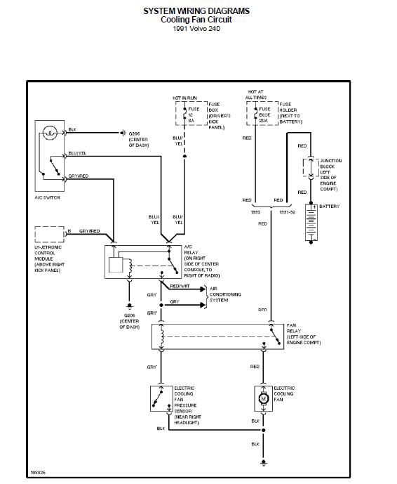
So I've got the complete wiring from a '92 244, for the A/C system, and I'm trying to implement the system in my LH2.2 equipped '85 245.

There are two wires in question....the gray wire and the green wire...the two wires that go to the engine bay pressure switches....they both snake back to the harness connector/to the LH2.4 engine harness.

I know there are two unused leads in my LH2.2 pigtail, under the dash, that are supposedly for A/C...

Can anyone confirm how to properly wire these?
 
Forget anything associated with the original AC setup. I'm sure you can use them one way or another but its best to just cut to the chase and use the AC wiring as it was with the orginal (92) setup.

GRAY: There is a 3-pos plug from the AC relay inside. This goes through the firewall and to a black 2-pos connector (around the strut tower) that takes it to the AC pressure switch at the drier/accumulator. Splits to the AC fan relay as well.

GREEN: Leaves the pressure switch and goes to the compressor.

Any of the wires that originally went to the LH2.4 ECU (in the 92 vehicle), just ignore.

I've done this conversion / swap about 12-15x now (no joke). Works quite well.
 
Last edited:
The set of gray wires on the '91 a/c are used to run voltage to the A/C fan relay for the aux fan, and then another gray wire from the relay to the A/C pressure switch (grounds the relay) that 's in the high pressure side of the line coming out of the condenser. The green wire is provided to the pressure switch located on the accumulator dryer on the passenger side of the bay near the firewall. From this switch the green wire powers the compressor clutch.
Here's the fan circuit, which should help. On my '91 I use the gray wire to ground my 940e-fan when the A/C pressure goes high, and replaced the 91 aux fan relay with the 8/9 series 2-stage relay. Also, it's important to use the gray/red wire in parallel to teh ECU so the IAC and ECU load control kicks in when the A/C is on. It also turns it off when you step on it:
1991240CoolingFan.jpg
 
Yes...

I went back to confirm the wires in question...

The green wire that goes to the compressor and dryer, also went to the LH2.4 ECU...

The Gray/Red wire from the dash 3-wire connector goes to the LH2.4 ECU..

Does one or both of these need to be hooked up? Where to on a LH2.2 car?
 
Alright...

I'm close, but could use a little more help.

I've got the LH2.4 pinout diagram here...

The two wires for AC, that connect to the ECU, are at pin #14(info. that A/C compressor is engaged), and 15 (info. that A/C control is on)

http://www.volvowiringdiagrams.com/volvo/LH%202.4/LH2.4%20ECU%20Pin%20Out.jpg


On the LH2.2 ECU pinout, there is only one connection, at pin #16 (status signal from A/C system)

http://www.volvowiringdiagrams.com/volvo/LH%202.2/LH%202.2%20Wiring%20Diagram.pdf

Soooo? Which, of the two wires, do I connect? The green one from the A/C compressor? Or, do I connect the gray/red one, that's tied to the harness, behind the center console?

Seems, the most logical thing is to connect the gray/red stripe wire to the LH2.2 box...

That way the LH2.2 computer knows when the A/C SYSTEM is on....the green wire will then just be left between the compressor and dryer switch, to engage the compressor....

I guess that last bit is irrelevant for LH2.2

Please confirm...

Thanks,

Myles
 
The 2.4/3.1 ECU's use that gray/red wire to know when to enrich the mixture under load while the a/c is on, and the green wire to activate or de-activate the a/c under high rpm or load, meaning in 2.4 the green wire goes through another switch in the ECU before it goes to the main a/c relay.
s4

So the only choice is the gray/red wire to 2.2 ECU and A/C relay tied together like the diagram below

In other words....disregard the green wire....it's only purpose is to engage the compressor, when the dryer is on?

I think I got it...just wanna be sure.
 
In other words....disregard the green wire....it's only purpose is to engage the compressor, when the dryer is on?

I think I got it...just wanna be sure.

Not 100% sure but think the 2.2 ECU uses that a/c signal for idle control only, so hook up like the diagram below

Edit: just took a moment to look at the two ECU pinouts you posted for 2.2 and 2.4

First the 2.4 diagram is for later 940 ECU's like 935, 936 etc, and has the fan control pinouts which a 240 ECU doesn't have, pretty sure the 92 240 doesn't have this ECU pin-outs.
The main purpose for the two inputs at pins 15 & 16 are for getting the IAC motor valve position so the idle doesn't stumble. This circuit is the same for 3.1 and one input, pin 16 comes from the A/C microswitch switch directly and the other comes from after the time delay of the A/C relay.
If I were to choose one wire, I would use the one from the time delay relay, probably hte green wire, but check the LH 2.4 240 wiring diagram first.
This would really depend on which ECU you want to use, and assume since it's a 2.4 harness that you are using a 561 or 951 ECU, so it all connects like the diagram as intended in the '92
Also no reason why you can't use a 935 ECU from a 940 n/a as they work better.
 
^

I'm using a 541 ECU...

It's an LH2.2 turbo 240...

As for the e-fan...I think the pinout would be the same, maybe...but I know that you can plug in the two pins and go go go, for an e-fan on LH2.4 240's.

So as to not impact idle, premature, use the green wire...so it'll only change when the compressor is on? Is that your recommendation?

Ahh, more information, that complicates it some. I don't think you can use the 2.4 harness from a 240 to support a turbo 2.2 car w/o some major rewiring. It would be easier to use a 936 ECU from a 940T and hook it all up like it should be.
Why go to the trouble if not going to a complete 2.4 system?

IIRC only 9xx ECU's suppoort the e-fan and the only 2.4 240 ECU that could have it is the 951 but isn't good for a +turbo.
 
Whoa, hey....

I may have steered you off course.

This isn't by any means a LH2.4 car....I'm trying to understand what the A/C system in an '91+ 240 did differently, in communication with its ECU, that the earlier cars didn't

It's a Factory Turbo car, converted to LH2.2...It's an '85 NA replacement harness, EZK ignition harness, combination....nothing for us to scratch our heads about there...

It's pin #16 that's relevant to this discussion....the only signal my LH2.2 ECU cares about, with regards to my new A/C system.

However, in the '92 240, the A/C system came from, which ran LH2.4....there was a second wire that went back to the ECU.

I was only referencing those diagrams, as, so far, they've been the only direction as to what these wires are for.

So the only thing that's "LH2.4" is the little bits of wiring that make the A/C system work.
 
Hey, do your homework. I just looked at the 91-93 240 ECU pin-outs and they are well marked 2.4 and 3.1:
http://www.volvowiringdiagrams.com/volvo/240 Wiring Diagrams/Volvo 240 1992.pdf

Pin 14 = A/C system green wire
pin 15 = A/C delay relay gry/red wire

The input from the delay relay starts the IAC operation, not engagement of A/C

In 2.2 the A/C doesn't use a delay relay so the green wire is the choice to go to pin 16
http://www.volvowiringdiagrams.com/volvo/240 Wiring Diagrams/Volvo 240 1988.pdf

Either way you're better off getting a 2.4 AMM, ECU and CTS and leave the 2.4 harness alone.
 
Well I was doing my homework...then I started asking questions...

LH2.4 seems like it'd be further away from me than you say...

Without a crank position sensor at the flywheel and all that jazz, I wouldn't know how to make that work, or over ride the tone ring diff stuff...no thank you.

So since I now have a AC delay relay, I can wire that lead to my ecu for idle control?

I'm just lost in the specifics of which signal will properly activate my idle control on my LH2.2 computer...sounds like I could go either way though.
 
Now you know why I'm confused. It sounded like a 2.4 conversion, but it's neither 240 2.2 or 2.4.......as LH 2.2 turbo doesn't exist.


Sorry for that confusion...complete AC system wiring for a LH2.4 car, as stated in the OP.

As for the engine harness....there's been no change to the pinout of the connector when going from LH2.2 na to LH2.2 turbo in this 240...

I think the "TURBO" element is irrelevant to this discussion.
 
I'm about to start on this swap as well, but mine is going into 2.0, which uses one wire to #16 as well. Did you ever decide on which of the two (green or gry/red) to use?
 
Back
Top