• Hello Guest, welcome to the initial stages of our new platform!
    You can find some additional information about where we are in the process of migrating the board and setting up our new software here

    Thank you for being a part of our community!

Milling piston crown of late model NA piston

Joined
Aug 23, 2020
Location
Netherlands
Hello everyone,

I am currently stepping up the game a bit with my turbobrick. I have a '91 B230F+T setup that is currently getting some head work and rods. The setup will be:

- B230F '91
- Maxpeeding rods
- 530 head with 46/38 stainless valves
- IPD Cam with KLRacing 39KG valve springs
- KLRacing intercooler (late style 940 type)
- Megasquirt 3 ECU
- Siemens Deka 630CC injectors
- 16T turbo with 3" downpipe / 2.5" exhaust system
- 90+ exhaust manifold, stock B230F intake manifold

The engine has to run on 93AKI/98RON fuel and i would like to up the boost a bit. Currently it runs fine at 15psi without any signs of detonation but i would like to up the game a bit later on by upgrading to a G25-550 turbo and increasing the boost to about 20~22psi.

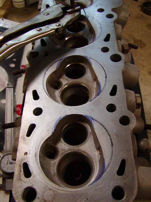
I calculated that the current compression ratio is about 9.6:1 when assuming the 530 head volume is 51.7cc. This seems to be a bit on the high side for my power targets at pump gas.

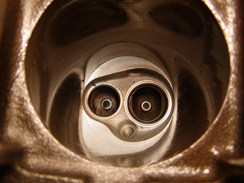
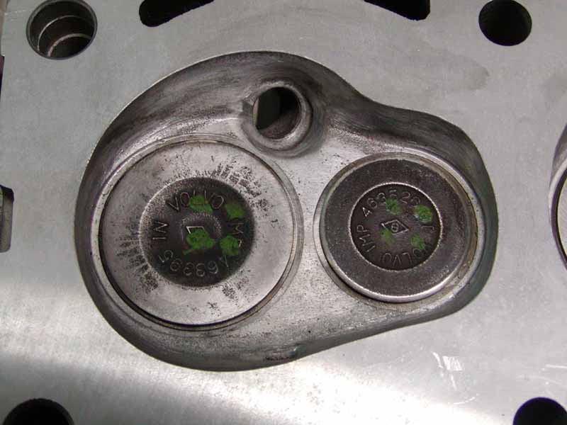
Deshrouding the valves and doing a small bit of work on the combustion chambers would hopefully net me about 3cc of additional volume but that isn't really enough to drop the compression ratio to the levels i need.

So i measured the NA piston crown thickness which is ~7.4mm. I would like to mill a small bit of the piston crown to make the dish 0.4mm deeper and increase the dish radius from 68mm to 75mm since the squish band on the 8V combustion chamber isn't really that wide. Milling the piston dish would net me another ~3cc of additional volume which combined with the head work would net me a compression ratio of about 8.8~8.9:1.

Is there any experience with milling down the NA pistons or is this really a no-go area? I would like to hear your opinions/experience. :nod:
 
I don't have experience with milling pistons as you asked, but I do have experience with the chamber volumes. The stock, untouched chambers in 530 heads I have measured with stock valves in them come out to 54.5cc, +/- a little bit, <1cc. The difference in the shape of the valve head faces you have chosen will reduce the chamber volume marginally.

My advice would be this: considering you're looking at doing something somewhat unusual, it's best to make sure of all of your measurements and leave nothing to chance. I would fully prepare the head and then calculate compression ratio. From there you can plan a best course of action.

You may be looking at a small enough number that an operation like this is unnecessary. For example, a 0.030" head gasket is about 5.5cc, where a 0.040" head gasket is about 7.3cc. Either one puts the squish in the accepted range for detonation resistance, while providing a fair amount of compression ratio change.

I would also advise to seek other opinions. I like the combination you've chosen and hope you keep us updated on it.
 
I?d unshroud the chambers vs machining the pistons. You can easily get to 8:1 with F pistons and modified chambers.

It is common practice to machine turbo pistons 3mm shorter when using a 86mm crank. The turbo pistons have more material and a lower ring placement.
 
How much will it cost to remove the pistons, have them milled, then reinstalled, vs just purchasing quality low compression forged pistons?

Iirc, the 8v head?s don?t respond well to messing with the quench distance unlike the 16v head.
 
Leave the piston height.
I removed .100" from dished pistons once but decked the block .120" to get more quench and higher compression.

Deshroud the valves a lot using a ball shaped burr or a fat round-end burr. Be careful, do lots of layout marking, and remove one curve x 4 chambers at a time. Deshroud both sides of the exhaust, but only the exhaust side of the intake. Deshrouding the short turn side doesn't help as much going in.
Also pay a lot of attention to the exhaust short turn, and the rest of the exhaust port and bowl.
 
My advice would be this: considering you're looking at doing something somewhat unusual, it's best to make sure of all of your measurements and leave nothing to chance. I would fully prepare the head and then calculate compression ratio. From there you can plan a best course of action.

You may be looking at a small enough number that an operation like this is unnecessary. For example, a 0.030" head gasket is about 5.5cc, where a 0.040" head gasket is about 7.3cc. Either one puts the squish in the accepted range for detonation resistance, while providing a fair amount of compression ratio change.
So it seems like it would be best to first do the head work and then see if i need those extra couple of cc's in the piston dish. For the head gasket i'm using an original style Elring gasket with stronger 10.9 grade head bolts. That gasket should be 0.047" thick according to tbricks knowledge. We have an in-house dyno so i'll keep you guys posted with results along the way.
I?d unshroud the chambers vs machining the pistons. You can easily get to 8:1 with F pistons and modified chambers.
It is common practice to machine turbo pistons 3mm shorter when using a 86mm crank. The turbo pistons have more material and a lower ring placement.
Do you happen to know the exact piston crown thickness of the turbo pistons?
How much will it cost to remove the pistons, have them milled, then reinstalled, vs just purchasing quality low compression forged pistons?
Iirc, the 8v head?s don?t respond well to messing with the quench distance unlike the 16v head.
The pistons are already cleaned up and laying on my work bench. Fortunately i can mill them myself so that would give me a net cost of 0$ which is kinda tempting. A set of forged Wiseco's with a 14cc dish costs ~?800 around here in the Netherlands and they don't install themselves unfortunately.
Leave the piston height.
I removed .100" from dished pistons once but decked the block .120" to get more quench and higher compression.

Deshroud the valves a lot using a ball shaped burr or a fat round-end burr. Be careful, do lots of layout marking, and remove one curve x 4 chambers at a time. Deshroud both sides of the exhaust, but only the exhaust side of the intake. Deshrouding the short turn side doesn't help as much going in.
Also pay a lot of attention to the exhaust short turn, and the rest of the exhaust port and bowl.
When machining the piston crown my intention is to keep the squish as-is since you guys found out the 8v head benefits from it. Only the dish will be made deeper and wider. The actually functional squish area will stay untouched. And thx for the tips for porting the head. I have access to a Serdi to cut the valve seats and do the initial radius for deshrouding the valves as much as possible to the sides of the piston wall. All the other stuff is still hand work unfortunately. I really don't know much about porting in general but a quick read through "David Vizard's How to Port & Flow Test Cylinder Heads" book gave me a bit of insight in the basics of head flow and completely corresponds with your advice.
 
I did some work in solidworks and 3d printed a mould to mark the combustion chamber outline for porting. I took some inspiration from the book about porting 8v cylinder heads and the 531 head that was ported with help from Porsche. My idea is to keep the floor of the combustion chamber untouched but radius it further out to the outline. What do you guys think about it? Did i go too far on the exhaust side?

(pictures are clickable)
 
That's too much material removed from the exhaust side in my opinion.

If you remove that much material from the spark plug side of the exhaust valve, you will hurt flow. This is from more exhaust gas flowing through the spark plug side of the valve pinching (reducing) the faster flow coming from the opposite side of the chamber.

You want 6-8mm removed from the edge of the valve for full unshrouding. Anything more is going to hurt higher lift flow.
 
So after a couple of hours printing and adjusting the 3D drawing i came to a new result. I altered the shape a bit, especially on the exhaust side. And it can easily be mounted now using the valves. I'm feeling pretty good about this one, what do you guys think? :) Once it's good i'll share the 3D printing file here.


Pictures are clickable again.
 
Here?s a pic of what I?d consider the maximum amount of chamber unshrouding you?d want to do. It was done because another shop butchered the head when they installed 46/40mm valves in a completely stock head. Good news, owner is using a somewhat mild cam and a turbo, so you can focus on lower lift flow.

https://flic.kr/p/2mEboYa

MikeP, I?m curious to see your approach as well!
 
pics from 19 years ago showing a super-conservative approach aimed at making a head that works ok with an NA B21:

18288707.jpg


Note, I left the far side of the intake alone this (my first with a 530) time. It seemed open enough, but I use a ball to curve it now. This is still slab-sided all around with sharp corners. I had ported a few heads, mostly chev and pontiac and a few fords. But I had no idea on this head.

18288732.jpg


There was no way to get pics of the runner work, and I don't have pics of the bowls or the back-cut valves. The faces have been shined up a wee bit and you can see the rounded exhaust corners in the chamber. It also looks like I backed off on opening up the near-side intake area of the chamber.

19536846.jpg
 
I use the David Vizard bathtub chamber formula to determine deshroud amount. It's: radius from valve stem centerline=(chamber depth*coefficient of discharge)+(0.5*valve head diameter). Basically it works out to clearancing 5-6mm around the exhaust valve, depending on how much you've taken off the head. Very little comes away from around the intake valve using this method. Looks extremely similar to Mikep's pics above.
 
I'm actually looking forward to doing the chamber work, not sure how the pics will be. I also have been meaning to do some posrt pics, but I think someone already did a good job of those.
It looks like I might not be able to do the chamber work this weekend, though. I am doing some wiring. I want to use deutsch connectors to mate microsquirt to factory harness so the engine comes out easier. So I'm in the middle of that. Maybe I'll get on it Monday.

But if you lay it out and remember you are guiding and curving the air like a wing, and make it a bowl (hemispherical) so the exhaust (gas) doesn't have to turn as sharply to get under the partially open valve, that's a start.
The valve is only open at max lift for a brief time. It spends a long time opening and closing, comparatively speaking.
 
Last edited:
I've made some small changes to the shape again and now i am practising on a spare 530 head. I first marked the combustion chamber and then i went ahead with the carbide cutter. Some ink from the marker went under the 3D printed gasket but the outline is still very obvious. It isn't polished or anything like that but i do like the shape. I am aiming more towards achieving good low-lift flow since the mild B230 cams don't really have that much high-lift duration.


Any tips for smoothing out the ported surface? :roll:
 
I use a burr (coarse for aluminum), then stones, then hard-rolls, then flap sanders (which are available in 40, 80 and 120 grit..avoid 40..).
Stones tend to clog on aluminum, so do fine burrs. You can try oil or wax on stones, but some also resist clogging better. Very coarse stones are worse. High speed (heat) makes it worse.
You will find that the large flap wheels are better in large curved areas, and some get worn to a good shape for others.

https://www.aaabrasives.com/standar...idge-roll-716187-1-4-x-1-x-1-8-120-grit-stock

https://www.amazon.com/Abrasive-Sander-Rocaris-Aluminum-Sanding/dp/B08R2YX8WB
 
Back
Top